

Key facts at a glance
- Nitrogen oxide reduction with SNCR or SCR.
- Simulation of the injection to choose the best injection strategy and mixing element.
- Droplets and vapour phase shown together.
In many technical systems, NO emissions have to be reduced by SNCR (Selective Non-Catalytic Reaction) or SCR (Selective Catalytic Reaction) methods. That is why simulation tools are used to find the optimal injection strategy in a two-phase flow system and to evaluate the best mixing device.
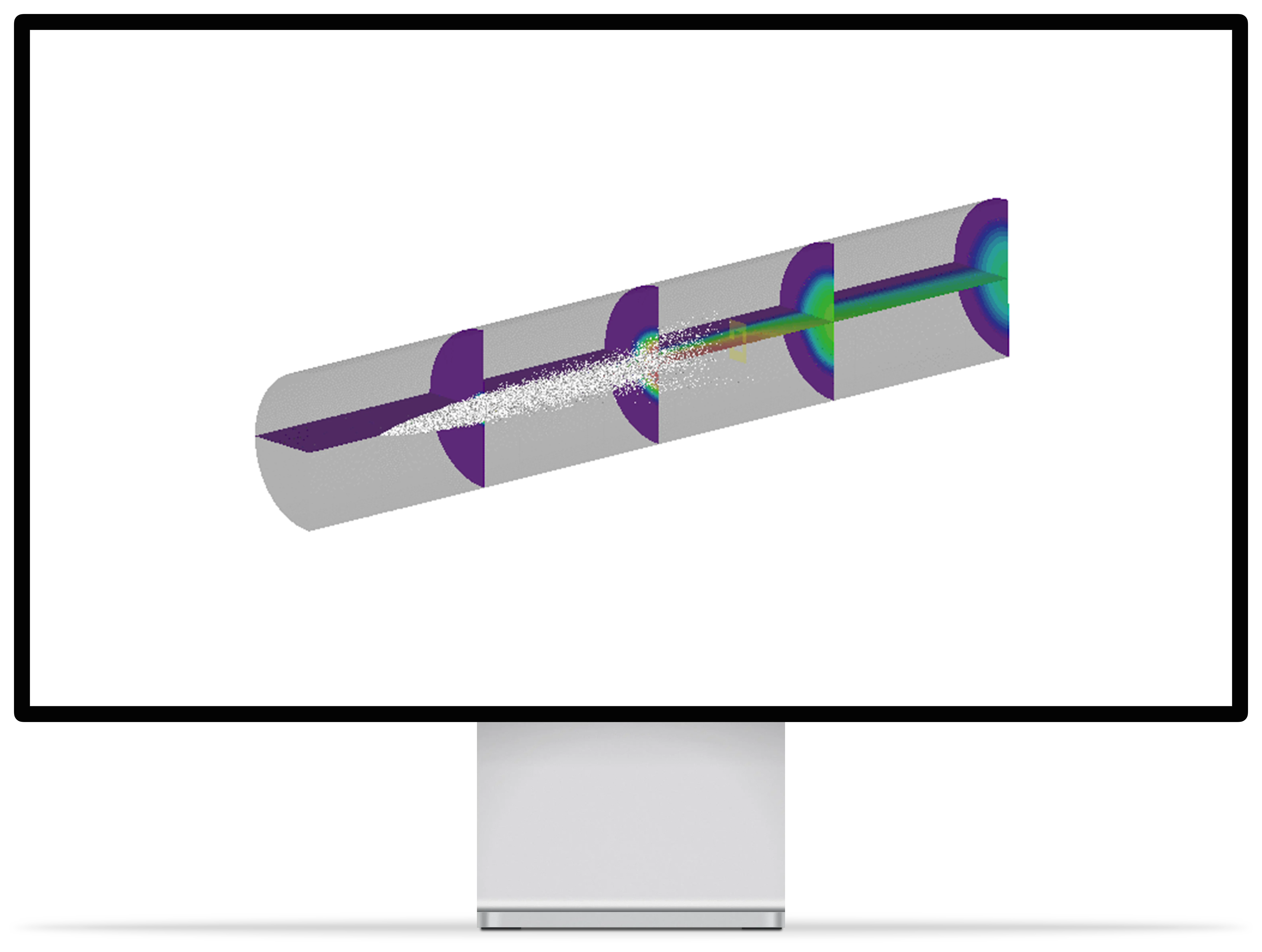
In the following image, the white dots show the liquid droplets of the injected flow and the colored planes show the distribution in the vapor phase.
What is SNCR and SCR injection about?
To reduce nitrogen oxides, a liquid reducing agent, such as a urea or ammonia solution, is injected into the exhaust gas. The droplets have to evaporate and mix evenly with the exhaust gas before the reaction takes place, either non-catalytically (SNCR) or on a catalyst (SCR). If droplets hit walls or the distribution is uneven, the effect decreases and deposits can form.
How do you proceed?
- Modelling the exhaust pipe, nozzle and mixing elements.
- Injection as droplets with evaporation and wall contact.
- Evaluating the distribution of the evaporated reducing agent across the cross-section upstream of the reaction zone.
- Comparing injection position, spray angle and mixing elements.
Frequently asked questions
How do you recognise a good injection strategy?
By an even distribution across the cross-section and as little wall wetting as possible.
Where is this used?
In combustion plants, engines and industrial exhaust gas systems.
Which results does the simulation provide?
It shows the droplet paths, the distribution of the evaporated reducing agent across the cross-section and the places where droplets hit walls. This makes it possible to compare injection position, spray angle and mixing elements before the plant is modified.
Further reading: Waste incineration · Liquid jets
Share Project:
High performance cooling of a charging cable for HPC/MWC application
View Project
CFD-Simulation für HPC/MWC-Ladekabel: Steckertemperatur um bis zu 35 °C senken
Optimierte Flüssigkeitskühlung senkt die Steckertemperatur um bis zu 35 °C und verlängert die Lebensdauer.
Projekt ansehen