

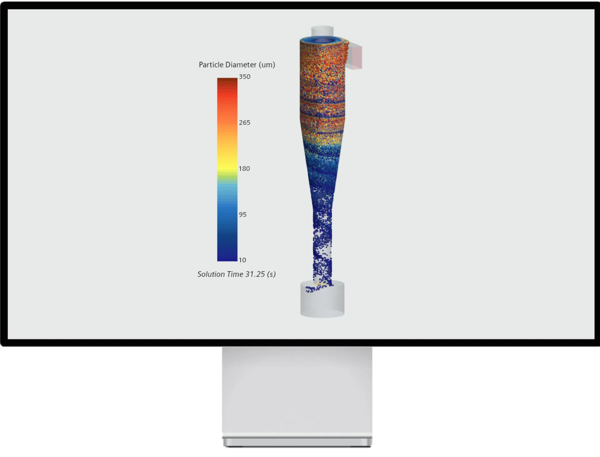
Particle Separation in a Cyclone by means of 3D CFD Simulation
ScrollKey facts at a glance
- Particle size distribution and air mass flow rate specified at the inlet.
- Interaction between particles and flow taken into account in both directions.
- Evaluated: particles in the collecting vessel and particles leaving the cyclone.
3D CFD Simulation of Particle Flow
In many applications the interaction between particles and the surrounding flow is important. The flow influences the pathway of the particles and on the other hand the particles may have an impact on the flow structure. So the two-way coupling must be considered.
The following example shows a cyclone particle separator. At the inlet face a particle size distribution and an air mass flow rate were assumed. The interaction between particles, flow and geometry of the cyclone allow investigating the particle size distribution and the number of particles in the collecting vessel (at the bottom of the cyclone). Furthermore, it can be analysed which particles can pass through (at the top face) and leave the cyclone to the neighbouring parts.
How is separation calculated?
Particles are introduced at the inlet with their size distribution and tracked on their way through the cyclone. At higher loadings, the particles act back on the flow, so the interaction is taken into account in both directions. The evaluation shows which share of each size class arrives in the collecting vessel and which leaves the cyclone.
What does two-way coupling mean?
At low loading, the flow moves the particles without being noticeably affected itself. As the amount of solids increases, however, the particles slow down the gas flow and change the vortex in the cyclone. Two-way coupling takes this feedback into account. This matters because separation efficiency and pressure drop shift together with the vortex.
What can be improved with this?
- Separation efficiency for fine particles through an adapted inlet or vortex finder geometry.
- Pressure drop at the same separation performance.
- Understanding carry-over or deposits in existing plants.
Frequently asked questions
Are design formulas not enough?
For proven designs, they often are. With unusual geometry or disturbed inflow, only the simulation shows where particles are lost.
Which data are needed?
Geometry, volume flow rate, particle size distribution and particle density.
Further reading: Liquid jets · Our services
Please don ot hesitate to contact us in case you need any further information (contact).
Share Project:
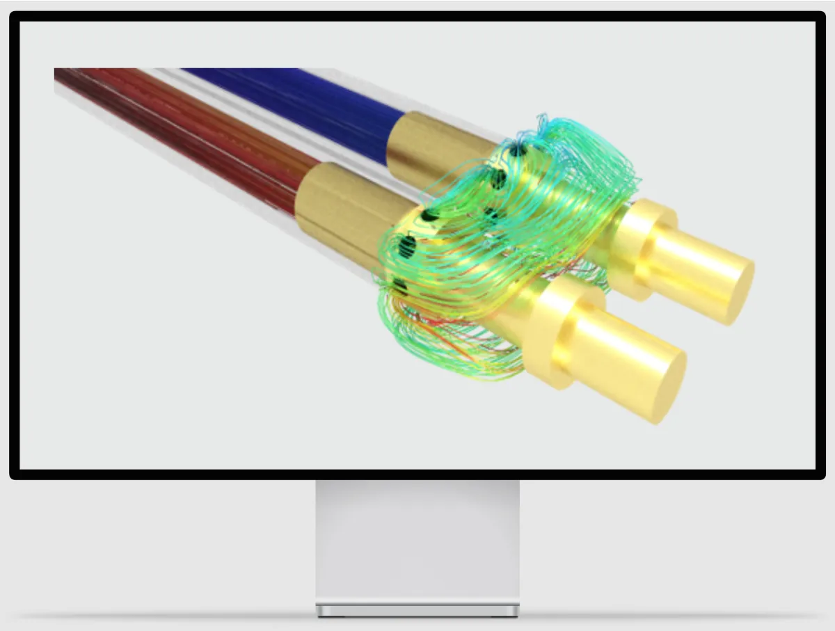
High performance cooling of a charging cable for HPC/MWC application
View Project
CFD-Simulation für HPC/MWC-Ladekabel: Steckertemperatur um bis zu 35 °C senken
Optimierte Flüssigkeitskühlung senkt die Steckertemperatur um bis zu 35 °C und verlängert die Lebensdauer.
Projekt ansehen